PLCopen State Machine
![]() A vendor -and product- independent worldwide association active in Industrial Control and aiming at standardizing PLC file formats based on XML the behavior of the axis at a high-level when multiple motion control
A vendor -and product- independent worldwide association active in Industrial Control and aiming at standardizing PLC file formats based on XML the behavior of the axis at a high-level when multiple motion control![]() Motion control is a sub-field of automation, in which the position and/or velocity of machines are controlled using some type of device such as a hydraulic pump, linear actuator, or an electric motor, generally a servo. Motion control is an important part of robotics and CNC machine tools; however, it is more complex than in the use of specialized machines, where the kinematics is usually simpler. The latter is often called General Motion Control (GMC). Motion control is widely used in the packaging, printing, textile and assembly industries function blocks are "simultaneously" activated. This combination of motion profiles is useful in building a more complicated profile or in handling exceptions within a program. In real implementations there can be additional states defined at a lower level.
Motion control is a sub-field of automation, in which the position and/or velocity of machines are controlled using some type of device such as a hydraulic pump, linear actuator, or an electric motor, generally a servo. Motion control is an important part of robotics and CNC machine tools; however, it is more complex than in the use of specialized machines, where the kinematics is usually simpler. The latter is often called General Motion Control (GMC). Motion control is widely used in the packaging, printing, textile and assembly industries function blocks are "simultaneously" activated. This combination of motion profiles is useful in building a more complicated profile or in handling exceptions within a program. In real implementations there can be additional states defined at a lower level.
The basic rule is that motion commands are always taken sequentially, even if the PLC![]() "Programmable Logic Controller"
A Programmable Logic Controller, PLC, or Programmable Controller is a digital computer used for automation of industrial processes, such as control of machinery on factory assembly lines.
Used to synchronize the flow of inputs from (physical) sensors and events with the flow of outputs to actuators and events has the capability of real parallel processing. These commands act on the state diagram of the axis.
"Programmable Logic Controller"
A Programmable Logic Controller, PLC, or Programmable Controller is a digital computer used for automation of industrial processes, such as control of machinery on factory assembly lines.
Used to synchronize the flow of inputs from (physical) sensors and events with the flow of outputs to actuators and events has the capability of real parallel processing. These commands act on the state diagram of the axis.
The axis is always in one of the defined states (see diagram below). A change of state is reflected immediately when issuing the corresponding motion command (please note that the response time of 'immediately' is system dependent).
There are seven states defined:
- Stand Still
- Homing
 The Homing procedure allows, based on a position measurement, to set a position offset to the motor in order to ensure it is physically at the home position
- Discrete Motion
- Continuous Motion
- Synchronized Motion
- Stopping
- Error Stop
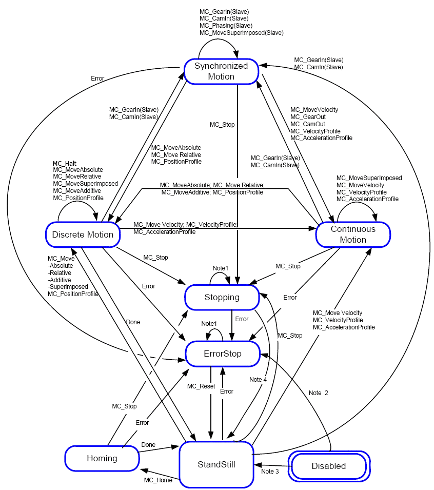
Figure 5-50: Motion State Machine (PLCopen)
-
-
Note 1: In this state ErrorStop or Stopping, all function blocks can be called, although they are not executed, except MC_Reset and Error which generate the transition to StandStill or ErrorStop respectively
Note 2:MC_Power FB is called with Enable=TRUE and there is an error in the Axis
Note 3: MC_Power FB is called with Enable=TRUE and there is no error in the Axis
Note 4: MC_Stop.Done and not MC_Stop.Execute
A normal procedure would start in StandStill. In this state the power can be switched on per axis (via the command MC_Power). Also, you can access the Homing state (via the issue of the command Home per axis), which after normal completion returns to StandStill. From here you can transfer an axis to either Discrete Motion or Continuous Motion. Via the Stopping state you can return to StandStill. ErrorStop is a state to which the axis transfers in case of error. Via a (manual) Reset command, you can return to StandStill, from which the machine can be moved to an operational state again.
Please note that the States define the functionality of the function blocks.
Function![]() A function calculates a result according to the current value of its inputs. A function has no internal data and is not linked to declared instances. Blocks which are not listed in the State Diagram do not affect the state of the axis, meaning that, whenever they are called, the state does not change. They are:
A function calculates a result according to the current value of its inputs. A function has no internal data and is not linked to declared instances. Blocks which are not listed in the State Diagram do not affect the state of the axis, meaning that, whenever they are called, the state does not change. They are:
- MC_ReadStatus
- MC_ReadAxisErr
- MC_ReadParameter
- MC_ReadBoolParameter
- MC_WriteParameter
- MC_WriteBoolParameter
- MC_ReadActualPosition
- MC_CamTableSelect
State Disabled
The Disabled state describes the initial state of the axis. In this state, the movement of the axis is not influenced by the FBs. The axis feedback is operational.
If the MC_PowerFB is called with Enable=TRUE while being in Disabled, this either leads to Standstill if there is no error inside the axis, or to ErrorStop if an error exists.
Calling MC_Power with Enable=FALSE in any state, the axis goes to the state Disabled, either directly or via any other state. If a motion generating function block controls an axis while the MC_Power FB with Enable=FALSE is called, the motion generating function block is aborted (CommandAborted).
Disable means power off without error.
State ErrorStop
The intention of the ErrorStop state is that the axis goes to a stop, if possible. No further FBs are accepted until a reset has been done from the ErrorStop state. The transition Error refers to errors from the axis and axis control, and not from the function block instances. These axis' errors can also be reflected in the output of the function blocks "FB instances errors".
Issuing MC_Home in any other state than StandStill goes to ErrorStop, even if MC_Home is issued from the Homing state itself.
ErrorStop is valid as highest priority and applicable in case of an error. The axis can have either power enabled or disabled, and can be changed via MC_Power. However, as long as the error is pending the state remains ErrorStop.
From StandStill to Stopping
Calling the FB MC_Stop in state StandStill changes the state to Stopping and back to Standstill when “Execute = FALSE”. The state Stopping is kept as long as the input “Execute” is true. The “Done” output is set when the stop ramp is finished.
StandStill is power on without an error.
The diagram is focused on a single-axis. The multi-axes function blocks (e.g. MC_CamIn, MC_GearIn or MC_Phasing) can be looked at, from a state diagram point of view, as multiple single-axes all in specific states. For instance, the CAM-master can be in the state Continuous Motion. The corresponding slave is in the state Synchronized Motion. Connecting a slave axis to a master axis has no influence on the master axis.


